Hardware Hacking Pt. 2 - Getting Started for less than £10... Honest...
Hardware Hacking - the Basics Pt. 2
NB Like pretty much everything on my site, I’m not writing this for the technically uninitiated. Fair warning, if the first few bits are hard, it’s probably meant to be that way. Pro tip - if you haven’t ever done any soldering, fix that first. I will assume a basic knowledge of electricity/rudimentary electronics here.
Also, some of this stuff may be controversial from the point of view of those who dislike cheap Chinese knock-offs.
Worked example for the uninitiated
Tools of the trade
To get started in hardware hacking, only two tools are really required;
- A Logic Analyser
- A USB to UART converter
Yup. That’s it. You can get the first from saleae, and they’re very reasonably priced, decent devices that are about the right price-point for entry level hardware hacking. However, there are also cheap Chinese knock-offs selling for £3.94p, that work with the software which Saleae provide for free. Yes, for FREE. So, do them a favour, and when you earn lots of money from hardware bug bounties, GO AND BUY A REAL SALEAE IF YOU HAVEN’T!! But I promised to have a blog post that shows you how to get into this for under a tenner, and I mean it.
Second is a USB to UART converter. Yes, you can get these for £6 on Amazon, but on AliExpress and at time of writing they are from around £0.82p, and that’s for ones using the CP2102 chip (which I would recommend).
So, assuming that you have the following devices:
- Soldering iron
- Solder
- Some insulated wire
- Multimeter
- A USB male to mini-USB male cable (to connect to the logic analyser)
The only other thing you may need to buy are some taps - these are little clips you can use to ‘tap’ onto the legs of IC’s. Here are some examples; search for ‘test folder’ or ‘test hook clip’. These are usually about £1.18p.
So, the grand total cost, £5.94p, if you don’t mind waiting up to three weeks for delivery and no guarantee that the stuff will work, is basically what it takes to get started on hardware hacking.
But what can we do with these?
Well, first off, find a device. Any device. Go on amazon, which will helpfully tell you which devices are the ‘most popular’. Look at those.
Murphy’s Law of IoT:
“The router/camera/internet toaster in your home, with access to all your data, was made by the lowest bidder…“
We’re in a scary world, device wise, and you’re about to see how bad it really is. The basic methodology is this:
Step 1. Identify developer headers
Developer what-ers? Developer headers. They are the serial connections used to debug devices when in production. For a gallery of what to look for, see this google image search for ideas. What you’ll want to do is to solder some wires or pins onto these, having removed the solder first. If you’re not sure how to do that, there are lots of videos/tutorials online. Just remember to tin wire ends before soldering, to make life easier.
Step 2. Analyse identified header pins
Ok, so now we’ve got a header, now what? Well, this is where it starts to get more interesting (and fun, in my opinion!). Find ground with your multimeter (one of the pins will have conductivity to the unified ground on the outer-collar of the power supply for example) and put that pin to the ‘GND’ pin on the logic analyser. Then put the rest of the pins to successive channels, plug in the analyser, and open up Logic.
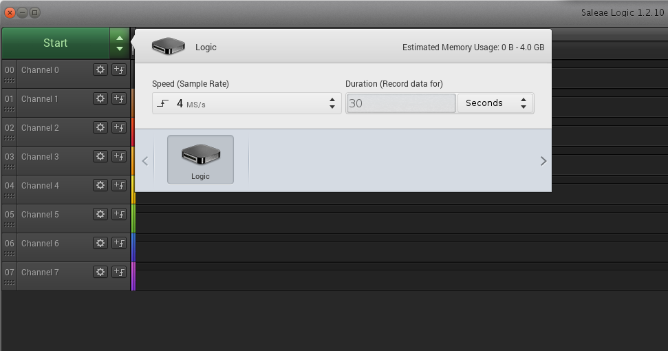
We now need to set the sampler, as follows:

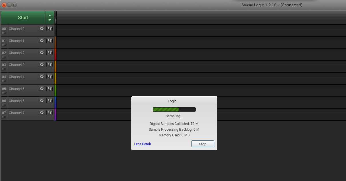
This will set the analyser to collect 4 million samples per second, for a duration of 30 seconds. So, with this set, let’s get some data! Press the big ‘Start’ button, and then turn on the router (yes, do it that way round). You’ll see Logic running…

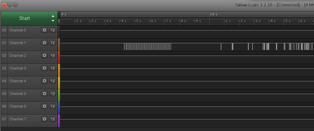
…aaaaaand then it’ll finish, and you’ll have some sampled data! \o/

Step 3. Identify pins and data about data transfer
Ok, so we’ve got some binary data. This, by itself, doesn’t mean much. So we need to recap how UART (Universal Asynchronous Receiver/Transmitter) protocol works. Essentially, there are two ‘data lines’, power, and ground. The data lines are ‘Tx’ for ‘transmit’ and ‘Rx’ for ‘Receive’. The Tx pin of one side goes to the Rx pin of the other, and vice versa. On a standard ‘8N1’ setup, the protocol operates in the following manner:
- The transmitter first drives down the voltage of the line. It’s held high by default, so this tells the receiver to ‘pay attention’ and this initial ‘0’ is called the ‘start bit’.
- The transmitter then drives changes in voltage from high to low to represent ‘1’ and ‘0’ as required by the data they want to transmit.
- After 8 bits have been transmitted, a ‘stop bit’ of ‘1’ is sent, essentially raising the voltage to how it was, and then not transmitting any more data.
The system is now ready for the process to repeat all over again, on either line. Here’s a nice little diagram of this from embedded.com

But how do the devices regulate their data transfer?!? Good question - Suppose we want to send ‘11111111’; how does the receiver know that it’s 8 ‘1’s and not just a long stop bit? Well, in short, it depends on the serial protocol in play. Most serial protocols have a ‘CLK’ or ‘clock’ signal that is used for timing of changes in bits. In UART, however, we choose a fixed bit-rate, or ‘baud rate’ with which to transfer data.
This baud rate can be literally any value at all, but in the interests of standardisation there are many common baud rates. The most common you’ll see in IoT devices and routers and the like are:
- 9600 (commonly used by arduino)
- 115200 (most common on routers and IoT device UART ports)
- 57600 (the other one I’ve seen the most).
There are lots of online lists of these, and where they are found. But how do you KNOW?!? Well, in short you don’t. There are two easy ways to identify baud rate:
- Read the datasheet for the chip you want to talk to.
- Guesswork/bruteforce the baud rate by trial and error.
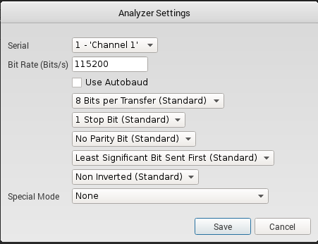
Yes, that may sound very inelegant, but it doesn’t take very long. The easy way is to just experiment on the samples you collected earlier using the built-in ‘Analyzers’. Look at the right of the screen in Logic, and you’ll see a little box in the middle of the right-hand pane called ‘analyzers’ - click on the ‘+’. The following screen will pop up:

So, first, assign the channel - in my example, it would be ‘Channel 1’. Then choose a baud rate. Start with 115200, then try 9600, then try 57600, then google for the others and try those. However, it’ll be really obvious when you’ve got it right, because in the lower right-hand pane labelled ‘Decoded Protocols’ you shouldn’t see any weird characters, like decimal ‘2xx’ references, etc.
When this works, and if you’re curious, you’ll also be able to zoom in (mouse wheel) to a part of the digital signal and see where characters have been identified, like this:

You should be able to make out version 1.04 in the blue boxes above the signal. Kinda cool, right? Well, Saleae have done a really nice job on this software, so they deserve credit for it!
Step 5. Connecting up the UART
So, you’ve got your USB to UART converter, and you’ve soldered on some wires/pins and identified which is Tx, and with your multimeter, you can work out which of the others is Rx and +ve (Hint the one with the higher voltage is usually the power rail. If it doesn’t work, try swapping them…).
Now what?
Well, you connect! How? Just use screen.
What, screen? The one I use all the time to run things over ssh?
Yeah, that screen. When you plug in the USB to UART converter, you’ll get a new device. I use linux, so it’s /dev/ttyUSB0. We know the baud rate, so the structure of our command will be screen /dev/ttyUSB0 (baud rate) or in this example screen /dev/ttyUSB0 115200. So, connect the converter, fire up screen, turn on the device, aaaaannnddd….
(Hacker Voice) We’re in
[Oh you use Windows? I’m so sorry. Have you tried using a real operating system?
LOL… jk… I just have no idea how to do any of this on windows. Sorry. (not sorry) ]
So, now you may see a prompt such as ‘press any key for terminal’. Or you’ll just see something like
@devicename#
Which, yeah… is a root shell. Wait, a r00t shell!? Yeah, a root shell. Many of them default to booting to root because that’s what you need when you’re debugging. All that text you saw flying past? Well, that’s known as the bootlog and that’s full of very, very useful information including
- Chip ID’s,
- kernel versions,
- gcc versions,
- service server/daemon versions including
- linux build dates,
- webserver versions,
- ACS/TR069 versions,
- wpa_supplicant settings,
and much more. Plus, having a root shell gives you acces to:
- source code,
- stored passwords in /etc/passwd and /etc/shadow files,
- full configuration files
- …yeah, the works.
But I’m a pentester… how can I use this more?!?
If you have to be told that, then this blog probably isn’t for you, but here are some ideas:
- you now have access to the firmware bootloader at startup. You can setup a tftp server and get the device to dump its firmware directly to you
- you can test for RCE exploits by just writing to this terminal with something like
input"; echo "test123" > /dev/ttyS0;and keeping an eye on the console. - Editing configuration files in the back end
- flush
iptables - …let your imagination fly…
Oh, and this is only through UART. There are other ways to hack hardware that vary in complexity, but for the effort to cost to benefit ratio, getting access to a UART port is superb. Well worth the slog!
Dirty Tricks
Sometimes manufacturers will play dirty tricks. Here are a few I’ve seen:
- They will include two resistors on development/prototyping boards to permit access to a UART header, then ‘leave these out’ on production builds
- nothing a quick bit of solder to bridge the gaps won’t fix, just a matter of finding them
- Some boards detect if UART listeners are present, and deactivate the header (thanks Virgin Media Superhub)
- Some manufacturers actually remove these development headers (ONCE! I’VE SEEN IT ONCE!)
- Often, you won’t have nicely laid out pins, but rather, a plethora of ‘contact points’ - just metal circular pads that you can solder onto.
- I know how to connect to these, but it’ll take a video, I think.
Thoughts and Feedback
Do get in touch over twitter or any other media you find me on and let me know what you think!
I hope it was in some sense useful. M.